
Headworks Cracking Risking 3 Highest Level FERC Category 1 Potential Failure Modes? New Design Flaws Discovered?
FREE Catholic Classes
Evidence of multiple serious Design Flaws in the Headworks Radial Gate Structure? Diagonal cracking in the end Piers in the Spillway, including a Large 14 foot crack in one of the 5 foot thick piers confirming this serious Flaw? Chipping of the bridge abutment concrete risking a spillway bridge collapse? Is there a legal liability exposure by reputable professionals or construction companies regarding a damage contribution to these serious FERC Category 1 PMF Failure modes?
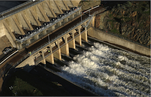
Will Construction use of Spillway bridge create new Radial Gate Headworks risks?
LOS ANGELES, CA (California Network) - The Federal Energy Regulatory Commission (FERC) requires Potential Failure Mode (PFM) assessments at dams in a process to proactively identify modes of "potential" failure as a method to ensure appropriate safe operating performance margins [21]. PFM's are an integral part of the FERC Dam Safety and Surveillance Monitoring Reporting process (DSSM's). High Reliability Systems, such as a dam and a spillway structure, require a constant assessment of conditions where FERC and the dam owners cooperate in this proactive DSSM's based exercise. Thus any findings requiring actions, whether further assessment or structural remedies, provide safeguarding the level of failure probabilities to "As Low As Reasonably Practicable" (ALARP)[20]. Civil law is based on this principle when entering into "controlling risk as effectively as possible" (See Fig 4).
Another critical component to Civil law and Risk Liability is noted as "standard of care" (SOC). Engineers have a duty to provide their services in a manner consistent with the 'standard of care' of their professions [19]. J. B. Kardon notes: "A good working definition of the standard of care of a professional, derived from case law (City of Mounds View, 1978; Gagne, 1934, and others), is presented in a standardized jury instruction, Book of Approved Jury Instructions, 6.37, "The Duty of a Professional," (BAJI, 1986), which reads: In performing professional services for a client, a professional has the duty to have that degree of learning and skill ordinarily possessed by reputable professionals, practicing in the same or similar locality and under similar circumstances. It is his or her further duty to use the care and skill ordinarily used in like cases by reputable members of his or her profession practicing in the same or similar locality under similar circumstances, and to use reasonable diligence and his or her best judgment in the exercise of professional skill and in the application of learning, in an effort to accomplish the purpose for which he or she was employed. A failure to fulfill any such duty is negligence."
What does all of this have to do with Oroville dam? Everything. These conditions establish the framework for legal liability and duty bound responsibilities by engineers, professionals, and contractors working on high risk structures such as at Oroville Dam. This framework includes the application to professionals that "practice" their services whether through consulting or through contract work. The specific application of these standards become relevant in the case of a "reasonable skill, possessed by reputable professionals" in light of an exposure to Potential Failure Modes (PFMs). This includes the obligation to recognize and appropriately respond to such PFMs as a "duty" whereby "A failure to fulfill any such duty is negligence.".
What if a contractor isn't notified of a PFM risk by the dam owner? Under Civil Law, the contractor still has a professional "duty" in the "standard of care" to exercise their expertise in recognition and awareness of such conditions within the reasonable performance of their services. Indeed, under these conditions, both the dam owner and the contractor could be held legally liable if a subsequent PFM occurs that is attributed to action (or inaction).
Why is this an issue? Because it can be reasonably established, by the history of DWR/DSOD Inspection reports, photographs, and archive design blueprints, that there are serious PFM failure mode "design flaws" that threaten the highest level of FERC Category 1 rated PFM's simply by "flexural load" use of the spillway bridge. Without immediate remedial action to these "flaws", the continued "load flexure" of the spillway bridge may induce up to 3 PFM catastrophic rated failure modes (See Fig 2). The California Division of Safety of Dams (DSOD) Inspector in January 12, 2000 identified a key spillway bridge design flaw where the bridge expansion joints do not have sliding "bearing pads" [12][11]. Thus, the expansion and contraction of the concrete spillway bridge slab would be "concrete on concrete" sliding on the Bridge Abutment column shelf support. This "flaw" has resulted in serious deterioration in "chipping" or "spalling" of concrete chunks at the seam that supports the spillway bridge. DSOD 2002 report notes: "An exception was the ongoing deterioration of the bridge supports, as shown in photograph 1. This is getting to the point where a repair should be considered." [13]. DSOD 2000 Inspector notes that HALF of the 11 inches of the support notch in the abutment has been chipped away in some locations ("The original support is 11 inches deep and we measured 5.5 inches of spalling in the worst location at the downstream right side of the bridge.") [12]. The DSOD inspector noted in calculations that 6 inches of support area was the minimum for load bearing. This only left -0.5 inches to the minimum margin. This was 17 years ago.
Year after year, DSOD Inspections monitor the continued "chipping" of this lip support by using orange/red paint to reveal new "chips" that have occurred [12][13]. Both ends of the spillway bridge have the same "concrete on concrete" sliding expansion joint and both ends have been recorded to have progressive "chipping" causing a narrowing of the bearing support area to the spillway bridge slab ends [1] (See Fig 3). With losses of up to 5.5 inches of bearing area concrete from "chipping", the spillway bridge risks a collapse from a heavy load crossing. Any heavy load crossing would thus risk tumbling a heavy vehicle directly on top of the Trunnion Gate anchorage, the Trunnion Radial Gate pins, and the Radial Gate itself (See Fig 2, Failure Mode 3). The damage could be significant to where this would be considered a "catastrophic failure" PFM mode.
Two other serious highest level FERC Category 1 rated PFM's originate from the very large diagonal shear cracking [14][15][16][17] (See Fig 2 - Failure Mode 1 & 2). This shear cracking is the result of another "design flaw" in that the original designers did not consider in the settling forces of the end bridge abutments into the substructure weathered rock at the abutment footing [10]. Thus the bridge abutment footing has a different footprint settlement profile compared to the large reinforced footing of the Flood Control Outlet Headworks monoliths. (See Fig 2). This "design flaw" is causing the diagonal cracking in the massive 5 ft thick Pier Columns as the columns have a small notch incorporated as a support for the spillway bridge. Thus a "settlement" of the bridge abutment causes the Pier Column notch to carry a focused load from load stresses on the spillway bridge slab. This downward focused load creates the "shear force". Indeed, a significant shear displacement at or near 4 inches is observed in the chamfer seam in the large 14ft + new 2ft "growth" of the Gate 8 pier 10 diagonal crack [9] (See Fig 1). The transfer of such a force to shear a 5ft thick reinforced concrete column would be significant. Both of the end Piers are documented in DSOD reports to have "diagonal cracking" at these corner notch points (See Fig 3).
Thus this "Shear Crack" differential force is transferred directly below to the Anchor Tendon plane (tendons embedded within the column) and also to the Trunnion Anchorage region & pivot pin. The "growth" of this crack is from the forces applied in "load flexure" from the spillway bridge. Therefore any further "load flexure" from any further spillway bridge usage will contribute additional stress that comprises the combination of the base "design flaw" (additional bridge abutment settlement & further forces on the pier notch). Anchor tendons at the Spillway are already of concern given their known "end of life" 50 year old age and the associated history of failures from these era of time [5][6][7][8].
Disturbingly, a 2015 DSOD report reveals that the cause of this serious "design flaw" has not been determined by DWR engineering [17], quote: "The long standing diagonal crack in the left pier for gate 8 appears to have extended to the concrete chamfer below the old telltale paint mark, as evidenced by the length of the recently applied red telltale pain, photograph 8. Visual monitoring of the crack should continue. A significant extension of the crack would warrant an investigation into the cause.". Any competent professional, in the field of skill of engineering, would easily recognize this "design flaw" from the blueprint drawings, and from the "as-built" performance of years of DSOD photographic evidence [2][3][4][9].
DWR recognizes the structural cracking risk and "load flexure" damage risk to the spillway bridge as evidenced from video footage & photographs of heavy construction vehicles moving less than 5 mph, centered on the bridge line, and only one vehicle on the bridge at a time. This operational condition would no likely be communicated to any other professional providing services or contracting work that utilizes the spillway bridge. The "duty" of "standard of care" would necessitate a professional awareness of these bridge operational requirements of a contractor whereby their professional skills would engender transfer of engineering information & discussion related to the structural concerns. Thus the contractor becomes enveloped within the definition of "a duty to provide their services in a manner consistent with the 'standard of care' of their professions".
If FERC was to be made aware of these "design flaws" and the serious potentially catastrophic PFM modes, the likely FERC action would be a response for immediate termination of any "load bearing" usage of the spillway bridge - including the complete shutdown of the bridge. In addition, FERC likely would initiate action regarding assessment of the structural impact of the generation of the combined 16ft long diagonal crack to determine if there is a related "reaction" fracturing (possibly including the foundation), and a risk assessment to the operational load capacity of the Pier from hydrostatic flows. Any "opening" of the shear fracture translates into an axis torsion of the radial trunnion gates to where a potential "binding" may occur.
With these serious PFM's (Fig 2), and the responsibility of the "standard of care" by professionals involved with the skill of their field in the FCO spillway, the "standard of care" response by any such services or contracting provider should be equal to the level of FERC standards to which DWR, as a dam operator, is licensed to conform to. J.B. Kardon notes: "The investigation must also take into account the fact that engineers are licensed or registered by the states in which they practice, for the purpose of protecting the public, and are bound by that license to act in a manner to fulfill that purpose. Additionally, the actions of engineers who are members of professional societies are defined or guided by those societies codes of ethics, and members are asked to perform in accordance with those codes for the purposes stated in them (Davis, 1998)."
Is DWR or any providing professional services contractor liable for a serious potentially catastrophic PFM mode from continued "load stressing" of the spillway bridge? Perhaps DWR should inform FERC, and any other professional services contractor, such as Kiewit, of these serious "design flaw" linked FERC Category 1 PFM's if they intend to use the the spillway bridge (i.e. "load stressing").
Note: text markups, underlines, arrows, on images and documents for illustrative purposes and are not part of the originals.
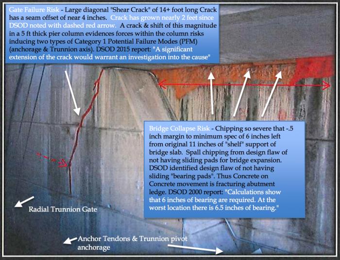
Fig 1. Over half of bearing support of 5 inches of concrete lost in areas from cumulative "chipping" (wide red paint area) in bridge support abutment. Heavy Loads may cause a sudden bridge failure. Design Flaw with no bearing plates causes "concrete on concrete" sliding induced fracture chipping. Growing diagonal crack due to another "design flaw". Threatens Trunnion Radial Gates & anchorage from shear forces and shifting of the 5ft thick Pier Column.
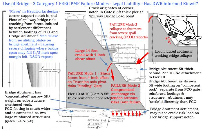
Fig 2. "Flaws in Headworks Design" - 3 serious FERC Category 1 PMF failure modes. Legal liability arising from "load flexing" of the spillway bridge? Will DWR inform Kiewit or any other engineering services contractors of these PMF bridge associated conditions?
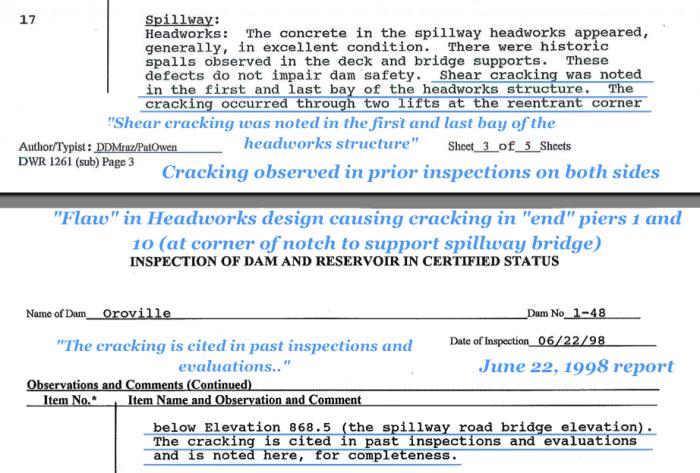
Fig 3. DSOD Inspection report revealing settlement evidence of Bridge Abutment "design flaw" as evidenced in diagonal cracking at the Pier support notch corner in both Piers 1 and 10 - shear forces created in notch by bridge slab from bridge "load flexure".
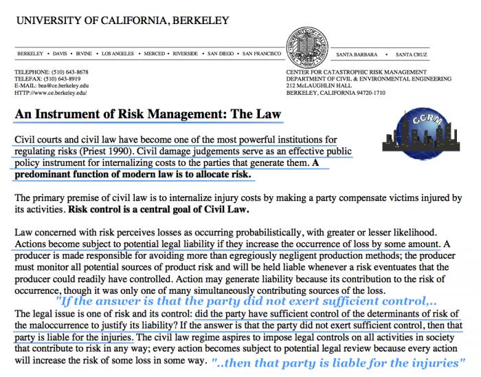
Fig 4. Legal implications in Civil Court and Civil Law regarding the "regulation of risk". Basis for determination of party liability from injury. Integral with safeguarding the level of failure probabilities to "As Low As Reasonably Practicable" (ALARP).
References:
[1] DSOD June 22, 1999 Inspection Report, Sheet 3, 06/22/98 - "Shear Cracking was noted in the first and last bay of the headworks structure. The cracking occurred through two lifts at the reentrant corner below Elevation 868.5 (the spillway road bridge elevation). The cracking is cited in past inspections and evaluations and is noted here, for completeness."
[2] HYD-510 report, U.S. Department Of The Interior, Sept 30, 1965, Fig 69, page 144 , Section B-B, Bridge Abutment, Spillway Bridge, FCO Pier - Report No. HYD-510 - https://www.usbr.gov/tsc/techreferences/hydraulics_lab/pubs/HYD/HYD-510.pdf
[3] The August 1, 1975 Oroville earthquake Investigations, page 292, Figure 182, Oroville Flood Control Outlet Structure Plan and Elevation, PLAN Bridge Abutment, SECTION A-A Piers 1-10, Monoliths 24-27 - https://archive.org/stream/august11975orovi20378cali#page/292/mode/2up
[4] DSOD Feb 3, 2015 Inspection report - Picture 8 - "Red telltale paint, left, marks the extent of a crack in the Gate 8 pier. The recently refreshed paint shows that the crack now extends below the dashed arrow to the concrete chamfer. Monitoring should continue."
[5] DWR Ultrasonic testing report 2000 - 28 anchor tendons with greater than 1/32 inch "reflector" flaws "considered significant" affecting all 8 Oroville gates - 12 greater than 1/16 inch, 1 very close to 1/8 inch "critical failure size" - https://elibrary-backup.ferc.gov/IDMWS/search/advResults.asp 20000419-0130(977645).tif
Failed Tendons - page 3, 4 - inferring 100% coverage by crack location of sample of 2 failed rods. Annular space between rods and protective pipes not properly grouted - Page 4. Water entered annular space through open grout ports - Page 4. It is "believed" that the rods were exposed to a corrosive environment over time as moisture accumulated within the unexpected voids. Page 4. The critical crack size in the case one of the Oroville rod appeared to be about 1/8 inch. - Page 4
[6] Trunnion Rod Microcrack Detection - US Army Corps of Engineers - http://www.dtic.mil/cgi-bin/GetTRDoc?Location=U2&doc=GetTRDoc.pdf&AD=ADA583523 file: ADA583523.pdf
"Post-tension rod loss occurs as an orthogonal brittle failure when a propagating cross-axial microcrack reaches a critical threshold. For ungrouted rods, this has resulted in rods being ejected under extreme velocities. Heavy retrofit cover box housings have been constructed to help contain failing rods. It is not known if the defect growth and resulting rod failure rate will stay at its relatively low number of a handful per year across the Corps inventory or whether it will increase as older rods continue to be in-service and defects continue to slowly propagate until reaching a threshold total failure point."
[7] DWR to FERC communications: December 27, 2013 https://elibrary-backup.ferc.gov/IDMWS/search/advResults.asp 20131227-5142(29015672).pdf
"By letter dated September 24, 2013, the Department of Water Resources (DWR) requested a time extension to address comments provided by the Federal Energy Regulatory Commission (FERC) on the 2011 Structural Re-Evaluation Reports of the radial gates for Oroville, Thermalito Diversion, Thermalito Forebay, and Thermalito Afterbay dams. Subsequent to DWR's request, engineers from DWR and FERC held a productive conference call on December 3, 2013, during which FERC engineers provided additional guidance. DWR understands that future re-evaluations should focus on failure modes (connections, buckling, trunnion shear, anchorage, etc.) that lead to catastrophic failure of the gate. The consequences of catastrophic failure should guide potential recommendations and any future warranted remedial actions."
[8] DWR Board concerned about failures -August 2014 DSOD Inspection report "Observation and Comments" - "The tendon anchors are about 50-years old and could experience problems in the future based on the history of tendon breakage at dams of similar age and construction. The Board expressed concern about this and will make strong recommendations about the need to carefully monitor and test the tendons using the latest tools. Ultrasonic testing of the anchor rods has resumed. At the suggestion of the Board, more informative testing methods are actively being pursued by O&M."
[9] Large 14 Foot Crack in Headworks? Cracking Radial Gate Steel tendons? Threat to Spillway yet no Repairs in 2017? - https://www.catholic.org/news/green/story.php?id=74915
[10] Structural Performance of Highway Bridges under Given Foundation Settlements - ASEE 2014 Zone I Conference, April 3-5, 2014 - http://www.asee.org/documents/zones/zone1/2014/Student/PDFs/95.pdf
[11] Bearings and Expansion Joints, Chapter 9, WSDOT Bridge Design Manual M 23-50.16, June 2016, http://www.wsdot.wa.gov/publications/manuals/fulltext/M23-50/Chapter9.pdf
[12] DSOD Jan 12, 2000 Inspection Report, Page 3, "Slow spalling continues beneath the road bridge, with recent spalls evidenced by missing red paint. Mr. Wolf requested an extension ladder so the remaining support could be determined. Mr. Wolf said that the cause of the spalling has been determined to be from movement of the bridge deck on the top of the abutment walls. There are no bearing pads so friction, probably from changing temperatures, spalls the edges of the support. The original support is 11 inches deep and we measured 5.5 inches of spalling in the worst location at the downstream right side of the bridge. Calculations show that 6 inches of bearing are required. At the worst location there is 6.5 inches of bearing. Overall we estimated that 3+ inches has been lost. Soon it will be time to design a fix."
[13] DSOD Jun 18, 2002 Inspection report, Sheet 2, "An exception was the ongoing deterioration of the bridge supports, as shown in photograph 1. This is getting to the point where a repair should be considered."
[14] DSOD Oct 12, 2005 Inspection report, Sheet 2, "The existing diagonal crack at the left bridge abutment is could be advancing. However, calcite at the end of the crack may be obscuring the monitoring paint. Crack monitoring should be continued. See photographs 12 and 13."
[15] DSOD May 6, 2008 Inspection report, Sheet 3, "The existing diagonal crack at the left abutment appears to be advancing somewhat. However, calcite at the end of the crack may be obscuring the monitoring pain. O&M will continue to monitor the crack."
[16] DSOD Sep 18, 2014 Inspection report, Sheet 2, "As noted during the last inspection, the diagonal crack on the left bridge abutment may have extended somewhat, but this could not be determined for sure due to the faded paint. The paint should be reapplied and observed regularly, as previously requested."
[17] DSOD Feb 3, 2015 Inspection report, Sheet 2, "The long standing diagonal crack in the left pier for gate 8 appears to have extended to the concrete chamfer below the old telltale paint mark, as evidenced by the length of the recently applied red telltale pain, photograph 8. Visual monitoring of the crack should continue. A significant extension of the crack would warrant an investigation into the cause."
[18] DSOD Sep 6, 2015 Inspection report, Sheet 3, "In response to the Part 12/DSRB report, the owner is currently consulting private firms that specialize in non-destructive testing (dispersive wave) to test the anchor tendons of the Flood Control Outlet (FCO) gates. This is a Category I Probable Failure Mode (PFM)."
[19] American Society of Civil Engineers 5th Forensic Engineering Congress November 10 - 15, 2009, Testifying Regarding the "Standard of Care", Joshua B. Kardon, PhD, Testifying Regarding the Standard Of Care.pdf
[20] An Instrument of Risk Management: The Law, ALARP, As Low As Reasonably Practical, Civil Law & Courts, Liability from injury, R. G. Bea, Risk and Civil Law-2.pdf
"Civil law has a primary objective of controlling risk as effectively as possible: As Low As Reasonably Practicable (ALARP). Courts have defined two fundamental principles of decision making to internalize costs to create incentives to reduce risk levels as much as practicable. 1. If injury could have been practicably prevented, liability will be placed on that part in the relatively better position to prevent it. 2. If injury could not have been practicably prevented, liability is placed on party in the relatively better position to spread the risks of the injury. The civil law concept is to create incentives to invest in risk reduction rather than to pay damages for unprevented injuries. In risk control, the main tests applied are: is the risk so great or the outcome so unacceptable that is must be refused altogether or; is the risk so small that no further precaution is necessary or; if the risk falls between these two levels, then has it been reduced to a level which is ALARP"
[21] FERC Potential Failure Modes, PMFs, https://www.ferc.gov/industries/hydropower/safety/initiatives/pfms.as
---
'Help Give every Student and Teacher FREE resources for a world-class Moral Catholic Education'
Copyright 2021 - Distributed by Catholic Online
Join the Movement
When you sign up below, you don't just join an email list - you're joining an entire movement for Free world class Catholic education.
An Urgent Message from Sister Sara – Please Watch
- Advent / Christmas
- 7 Morning Prayers
- Mysteries of the Rosary
- Litany of the Bl. Virgin Mary
- Popular Saints
- Popular Prayers
- Female Saints
- Saint Feast Days by Month
- Stations of the Cross
- St. Francis of Assisi
- St. Michael the Archangel
- The Apostles' Creed
- Unfailing Prayer to St. Anthony
- Pray the Rosary
![]()
Copyright 2025 Catholic Online. All materials contained on this site, whether written, audible or visual are the exclusive property of Catholic Online and are protected under U.S. and International copyright laws, © Copyright 2025 Catholic Online. Any unauthorized use, without prior written consent of Catholic Online is strictly forbidden and prohibited.
Catholic Online is a Project of Your Catholic Voice Foundation, a Not-for-Profit Corporation. Your Catholic Voice Foundation has been granted a recognition of tax exemption under Section 501(c)(3) of the Internal Revenue Code. Federal Tax Identification Number: 81-0596847. Your gift is tax-deductible as allowed by law.


